In this tutorial Let’s talk about a practical application of RTU5024 G.S.M controller . In this tutorial we are going to talk about practical use of RTU5024 controller with examples. You may have seen lot of gate opener applications using this controller. But , The applications of this controller is limitless . You can use it to control home lights , Water pumps , Fans , etc .. Even you can use it as a security device . However , each of these applications require different electrical components and wiring diagrams. Here in this tutorial lets find out how to use RTU5024 G.S.M controller in different applications with electrical diagrams.Whatever the application there are few things need to be consider before proceeding. Here are the things to consider . This will help you to arrange the required components for each application.
Controlling equipment Ratings
Controlling equipment means the device that is connected to the relay contacts of the G.S.M controller. These devices varies from application to application. E.g – Motors,Lights , Heaters , Alarms etc. . There are two main electrical ratings that we need to focus on .
Voltage Rating – Voltage rating is the voltage requirement of the device that we need to control. This voltage is the voltage that we need to supply through the contacts G.S.M controller’s relay . Any voltage that exceed the voltage rating of the device will damage it .If you supply a lower voltage , The device may or may not work. Check the voltage rating of the device before supplying voltage through the contacts of the RTU5024 controller.
Current Rating – Current rating is the electrical current that passes through the device as it works . The current ratings of your device should not exceed the current rating of the G.S.M controllers relay contacts . If so , You might have to use another relay or contactor to control the device . In this case the relay of the RTU5024 is connected to the coil of the relay or contactor . As the relay contacts of G.S.M controller touch each other the coil of the relay/ contactor (High current) gets magnetize causing contact points of it to make contact.Thus , Supplying power to the final output devices.
Controller Placement
It’s impotent to decide where to put your controller before doing the wiring . If your RTU5024 controller is not water proof , You have to place it inside a building . If you are using a non water proof controller outside , You must place it inside a water proof panel box with water sealing . Usually , The RTU5024 controller with metal housing is designed for indoor use only . The water proof RTU5024 controller comes with a plastic housing .
Wire requirements

RTU5024 wire length Calculation
There are two types of things you needs to consider when it comes to wiring . The length of the wires and type of the wires . Wire length consists of the length of the power supply wires , Wire length inside the controller panel (Controller wiring) and the wire length of the wire that connects the controller to the device . The type of the wire depends on the amount of current they carry . If the wires carry low amount of current , You can use wires with small diameter (E.g – relay coil supply wires). But , If the wires carry high current , You need high gauge wires . (E.g- Motor supply wires and Power supply wires).
Relay / Contactor requirements.

Contactor
There is a built-in relay inside the RTU5024 controller . However , The current rating of the contacts of this relay is too low to handle high current loads like water pumps . But , You can directly control the devices that uses low current such as lights and fans . If you wants to control a device that have high current rating , You must use a external relay or contactor that have higher contact current rating. In this case the RTU5024 controller’s relay connected to the coil of the external relay or contactor. Thus , The controller’s relay only have to deal with the current of the external relay’s coil .
Safety requirements
The most important thing when it comes to designing a electrical system is the safety measures . Since we are working with the mains voltages , You need to design your system with safety measures . In case of current leak , The system need proper earth connection . Any electrical connections should not exposed .Avoid connections between wires to extend wire length . However , If you are connecting two wires together , Make sure to properly insulate the connection area. If the wires runs underground use P.V.C tubing . Cover all the exposed electrical contact points . Use a panel with a key lock to place the controller equipment .
Protective Devices
Any electrical design requires one or more protective devices to protect the equipment and the people who are using them. Here are some of them and what are the purpose of them.
Residual Current Circuit Breaker (RCCB)

RCCB
This device will protect against leak current (Ground fault) . This device can protect any person that came into contact with any live part of the electrical system and it can prevent fire hazards by tripping the circuit if the system have damaged wires (damaged insulation of wires can cause current leak to the ground . Thus , Tripping the device ). Once the ground fault was corrected this device can be turned ON. The main parameter you need to look for is the tipping current (Eg 30mA , 300mA ). If the device that you are controlling have low leakage current , You must use a low (<30mA) or no tipping current RCCB . If your device have high leakage current ( > 100mA ), You can use a RCCB with high tipping current .
Miniature Circuit Breaker (MCB)

MCB
This is a device will protect the components in a electrical circuit in a case of over load or Over current . This device can also prevent fires that can caused due short circuit by cutting the power supply . The excessive current flow will cause the bi-metal part to turn off the mechanical switch inside . Once , The over current reasons fixed in the electrical system you can turn it ON by hand. However , The short circuit conditions where handled by a tripping coil inside this device . When selecting such device you have to consider few things such as the Type of the MCB , Rated current , Braking capacity and number of poles .
Fuses

Motor Fuse
Fuses do the same thing that MCB do . But , In a different way . Fuses will blew in a event of over current or short circuit . Thus ,You have to replace them in such case . However , It’s electrical characteristics are very different from a MCB’s electrical characteristics . Although , In newer electrical systems you will see a MCB or MCCB instead of fuses , These fuses are very common in old electrical control systems .
Thermal Overload Relay

Thermal Overload Relay
These devices will protect the motors in a case of over current . The bi-metals inside these devices will bend and trip the device in a set current . Unlike MCB or MCCB , These devices will automatically switched ON as the bi-metals cool down. They also have manual ON/OFF switch . As we have mentioned early , These devices have adjustable Tripping current . You can set it to a given value . Minimum and the maximum tripping current range , Number of poles are the main thing to consider when buying a thermal overload relay.[/vc_column_text][/vc_column][/vc_row][vc_row][vc_column][vc_column_text]
RTU5024 Gate Opener

This is the most famous RTU5024 application . In fact most people think RTU5024 is only a gate opener . In this application we are going to show you how to control a rolling gate using RTU5024 gate opener.
Mechanical Design
For this tutorial we used a geared single phase motor to open and close the gate .This is a rack and pinion type assembly. The gate have linear tooth (Rack) along the length. This linear tooth are in contact with the motors gear wheel (Pinion) . Since , These two are in contact, The rack will move in a linear direction as the motor rotates . Thus , Moving the whole gate . Although , The efficiency of this system is questionable , This is the most used sliding gate opener assembly .There are two limit switches at each end to stop the motor as it reach each end . In the gate there is a metal piece that will push the limit switches arms as it passes them. This system requires regular maintenance . Greasing the rack and pinon assembly is a must . You must allow some gap between rack and pinion gear wheel .In a case of stuck gate the motor wheel should be able to slip on top of the rack assembly to prevent any damage to the motor . You can also done this in the electrical system .
Electrical Design
In the electrical system there are mainly two circuits . The controller circuit and the motor power circuit .The controller circuit includes limit switches , Buttons , Indicators and G.S.M controller. The motor power circuit includes thermal overload , Relay contator and M.C.B . However , All these equipment are placed inside a single panel box except for the limit switches. The power supply to this system comes from the main distribution board . To stop the motor in a case of emergency , we have used emergency stop button . This control panel have both manual and G.S.M control of the motor. Here is the RTU5024 Gate Opener wiring diagram.
RTU5024 Gate Opener Power Wiring Diagram

RTU5024 Gate Opener Power diagram
This is the Power diagram of RTU5024 Gate opener. In this circuit we used a 3phase motor . Here are the list of items .
MCB1 – 3phase Miniature Circuit Breaker.
C1 ,C2 – Contractor Relays .
TO1 -Thermal Overload Protector.
M1 – 3phase motor .
In this diagram as you can see the main supply (3Phase) is connected to a MCB then the output of that MCB connects to each contactor relays . These are the forward and reverse motor drive relays . If C1 relay is active the motor will rotate in a one direction and if the C2 relay is active it will drives the motor in opposite direction. Thus , sliding the gate left or right (Gate Open and Close action). Both of these relays shouldn’t be activated at the same time . The control circuit is designed such way it will prevent power to both relays at the same time.The output of these relays are connected to a thermal overload protector . Finally , The thermal overload is connected to the motor terminals. You need to select the relay contactor , Thermal overload and MCB according to your motor ratings.
RTU5024 Gate Opener Control Circuit Wiring Diagram.

Controller wiring Diagram
This is the controller circuit of the above wiring . This diagram illustrate the control aspects of the above components. Here are the list of components.
PB0 – Emergency Stop button.
SS1 – 2 Way selector switch.
C1NC , C2NC – Contactor relay’s normally closed contacts .
C1NO, C2NO – Contactor relay’s normally Open contacts .
PB1 , PB2 – Gate Open Close Push Buttons .
LS3 , LS4 – Mechanical limit switches .
GC1 – G.S.M controller relay’s Normally open contact.
FC1 , FC2 – Relay Contactor coils .
As you can see the power comes through the normally closed Emergency Stop button and goes to the two way selector switch . This switch separates the manual and Auto (G.S.M) controller circuits.This allows users to select manual or G.S.M control . Because of this design , You cannot use both at the same time . The manual circuit divided in to two sections one section for forward motor drive and other is for reverse motor drive. There are two buttons for each direction of motor rotation . If you press one button , Other button press action will be ignored until the limit switch of the other side triggered.However , If you wants to move the gate in the opposite direction while it moves , Press the Emergency Stop button and press it again to reinstate it .Then , Press the Gate direction button you wants . Press the Emergency stop button to stop the gate anytime you wants to stop the gate . Use buttons that have voltage and ampere ratings that is equal or greater than the contractor coils voltage and ampere ratings. Use a suitable wire gauge to do the controller wiring.
RTU5024 Light Controller
 In this case we use a single RTU5024 G.S.M to control multiple lights. E.g- Remote house lighting system . Since , RTU5024 only have a single relay rated at 1 Aac . You have to use external relays if you are controlling more than a 1Aac light load . In this article , We are going to take a look at multiple examples of RTU5024 light control . Here is the wiring diagrams .
RTU5024 Light controller Wiring Diagram 1
RTU5024 Light controller diagram 1
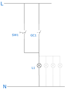
This is the simplest version of RTU5024 light controller. Here are the list of components used.
SW1 – One way one gang switch.
GC1 – G.S.M controller relay’s contact.
L1 – Light bulb .
You can use the SW1 switch to manually control the lights .If you turned the G.S.M relay on it will supply the power to the lights .You can connect multiple lights in parallel as illustrated in the diagram . Only problem is you cannot control each light individually. The sum of the current taken by the light load should not exceed the maximum current rating of the G.S.M controllers relay contacts.
RTU5024 Light controller Wiring Diagram 2

Light Controller Wiring Diagram 2
In this system we used four relays to control multiple set of lights .Here are the list of components used .
GC1 – G.S.M Controller’s relay contact (Normally Open) .
RL1, RL2,RL3,RL4 – External Relay’s coils .
L1 , L2 , L3 , L4 – Lights .
RL1NO , RL2NO …. – External Relay’s contacts (Normally Open)
Each relay’s normally open contacts are connected to a set of lights . The G.S.M controllers relay supplies the power to each external relay’s coil . Once the G.S.M controllers relay turned on , It will power all the external relay coils . Thus , supplying power to the bulbs connected to them. The sum of the current rating of all the external relay coils should not exceed the current rating of the G.S.M controller’s relay contacts. The sum of current ratings of bulbs should not exceed the current rating of the external relay’s contacts. There is no manual operation in this circuit .
RTU5024 Light controller Wiring Diagram 3

Light Controller Wiring Diagram 3
In this circuit we have both manual and auto (G.S.M) control of the bulbs . Here are the component list .
GC1 – G.S.M controller relay’s contacts (Normally Open) .
S0 – Two way One gang switch .
S1 ,S2 ,S3, S4 – One way One gang Switch .
L1 , L2 ,L3 ,L4 – Light Bulbs.
The S0 switch can be flip between manual and Auto (G.S.M) operation. If you select manual operation the lights will operate as you flip the S1 ,S2,S3 and S4 buttons . However If you selected the auto mode , The light bulbs will operate only when the G.S.M controllers relay is turned on . But , You have to select which bulbs to be turned ON/ OFF by flipping the S1 ,S2 ,S3 and S4 buttons .
RTU5024 Fan Controller
Fan controller is very similar to the light controller except it has regulator / Dimmers in series with the Fan. There are several ways we can use RTU5024 controller with fans . Here are the RTU5024 Fan controller wiring diagrams.
RTU5024 Fan Controller wiring Diagram 1
RTU5024 G.S.M Fan controller wiring Diagram 1
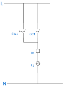
As you can see the supply to the fan regulator comes trough the one way one gang switch and the G.S.M controllers relay contacts .You have to set the regulator to a speed other than zero or OFF . You can use the mechanical switch to manually turn ON or OFF the relay .Here are the component list .
SW1 – One gang one way switch .
GC1 – G.S.M controller relay’s contacts (Normally Open).
R1 – Fan regulator /Dimmer .
F1 – Fan .
RTU5024 Fan Controller Wiring Diagram 2

RTU5024 Fan Controller Wiring Diagram 2
In this circuit each fan is connected to one way one gang switch. This allows each fan to be turned ON or OFF in both manual and auto modes . Auto and manual modes can be selected using “S0” button . The power comes through the selector switch goes to each fan’s regulator . Here are the components of this circuit .
CG1 – G.S.M controller relay’s contacts (Normally Open).
S0 – Two way one gang switch .
R1 , R2 , R3 , R4 – Fan regulators.
F1 , F2 , F3 , F4 – Fans
S1 , S2 , S3 , S4 – One way one gang switches.
The total fan current load should not exceed the G.S.M controller relay’s maximum current rating or the “S0” switch’s maximum current rating. If you are controlling a higher fan load , Use an external relay to handle the fan load .
RTU5024 Water Pump Controller

Water pump Controller
RTU5024 water pump controller is very similar to the Gate opener except for this circuit have a float switch instead of the limit switches in the gate opener circuit .Also , This circuit requires the motor rotation in one direction only .Thus , It has less components than the gate opener circuit. Since , The relay of the G.S.M controller cannot handle the current requirement of a water pump , We are going to use a relay Contactor to handle the motor (Pump) load .
RTU5024 Water Pump Controller Power Diagram

RTU5024 Pump Controller Power Diagram
This is the power wiring diagram of the RTU5024 pump .It’s very similar to the Gate opener application’s power diagram. But ,This circuit only has one contactor relay . Here are the component list.
MCB1 – Miniature Circuit Barker.
C1 – Contactor Relay .
TO1 – Thermal Overload Protector.
M – 3phase Pump .
The components should be selected to match the motor electrical ratings .
RTU5024 Water Pump Controller Diagram 1

Pump Controller Diagram 1
In this controller circuit , Both manual and G.S.M control present. There is no selection between the modes . Manual and G.S.M control both works same time . You can push the emergency stop button to stop the pump in any mode. Manual stop button will only works on manual mode. Here are the parts list .
PB0 – Emergency Stop Button.
FS4 – Float switch (Placed inside the tank ).
GC1 – G.S.M Controller relay’s contacts .
PB1 – Push button (Manual Start Button).
PB2 – Push button (Manual Stop Button ).
C1NO – Contactor’s Normally open contacts .
FC1 – Contactor’s Coil .
RTU5024 Water Pump Controller Diagram 2

Pump Controller Diagram 2
In this controller circuit the “SS1” selector switch is for the selection between manual and G.S.M control.Depending on the selection you made , It will be on a single mode only . Here are the parts list .
PB0 – Emergency Stop Button.
SS1 – Selector Switch .
FS4 – Float switch (Placed inside the tank ).
GC1 – G.S.M Controller relay’s contacts .
PB1 – Push button (Manual Start Button).
PB2 – Push button (Manual Stop Button ).
C1NO,C1NO2 – Contactor’s Normally open contacts .
FC1 – Contactor’s Coil .
Make sure to use wires with enough gauge to carry the current required for the operation of the relay contactor coils. The buttons current rating should be greater than the current rating of the relay contactor’s coil.
RTU5024 Water Pump Controller Diagram 3

RTU5024 Water Pump Controller Diagram 3
In this controller diagram we used a float switch to stop the motor in a case of tank overflow . The Contactor coil power goes through the normally close contact of the float switch . When the tank overflow this contact will open , Which will prevent the current flow to the Contactor coil. Stopping the motor.
PB0 – Emergency Stop Button.
SS1 – Selector Switch .
FS4 – Float switch (Placed inside the tank ).
GC1 – G.S.M Controller relay’s contacts .
PB1 – Push button (Manual Start Button).
PB2 – Push button (Manual Stop Button ).
C1NO,C1NO2 – Contactor’s Normally open contacts . FC1 – Contactor’s Coil . FS.1NC – Float Switch 1 (Normally Close)
RTU5024 Security System
Due to the limitations of RTU5024 G.S.M controller , Only system design we came up with is a system that allows you to remotely turn On or OFF the security system. This is not much .But, It can be help full when you are away but turn your security system ON/OFF remotely from anywhere in the world.
RTU5024 Security System Diagram
RTU5024 Security System Control
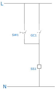
As You can see in this diagram The “SW1” switch is for manual control of the system. Only downside of this circuit is that If the security system is manually turned on , You cannot turn it OFF using the G.S.M controller.Likewise , If the security system is turned ON using G.S.M controller , You cannot turn it OFF manually. Here are the part list .
SW1 – One gang one way switch.
GC1 – G.S.M Controller relay’s contact (Normally Open).
SS1 – Security system controller device.
Conclusion
 Although , Everyone calls this device as a “Gate Opener” . This device can be used for almost any application . Since , This device only has one relay.The usage of this device is limited to simple applications. Advance applications are impossible.However , If you are good at Microcontroller programming , You can program an IC to communicate with the G.S.M controller and do anything you want. This way you can control multiple relays . Google search the G.S.M modules model number plus “AT Commands” for find the commands or refer to the G.S.M modules datasheet.
Frequently Asked Questions
Can I replace the relay of the RTU5024 controller ?
Yes , You can . Make sure to replace it with a relay that have a 5v coil .In order to solder the relay in to the PCB the physical pin arrangement should match.
Is there any other RTU5024 controller applications ?
Yes of cause , These are only few examples . There are many .You can use this controller to switch any electrical load .
Is there any G.S.M controller with multiple Relays ?
Yes, There are many. There are 2 channel (2 Relays) , 4 channel (4 Relays) , 6 Channel (6 Relays) and 8 channel (8 Relays) modules available in the market . Google Image search the term “G.S.M Relay Controller Module” and choose the module you wants .
Disclaimer – The content of this article may change over the time . Since , Different manufactures have different designs , The specifications mentioned may change manufacture to manufacture. This tutorial involves working with high voltages that may harm you and others around you .Take the necessary precautions before working with mains voltages . If you are inexperienced , please follow this tutorial under someones (person with experience) supervision .We are not responsible for any damages caused by following this tutorial. This tutorial does not provide any hacking or illegal activity.
Author : Senel Nanayakkara
Published on : 13|08|2021