Here in this article we are going to discuss different types of power supply built for RTU5024 G.S.M relay controller based project . You might ask why we need a power supply ? , The answer is , We need a Power supply to step down (Lower the voltage) the mains voltage to the rated voltage of the controller .Since , The Mains voltage is very high compared to rated voltage of RTU5024 . The type of the voltage also matters . This controller needs DC voltage . If your Mains voltage is AC that voltage needs to be stepped down and converted to DC voltage. However , If your mains supply is DC such stage is not necessary . These are the stages that required in a simple linear power supply . However there are other power supplies as well . In this tutorial we discuss what are the best type of power supply for RTU5024 and how to build the power supply unit for any G.S.M relay controller.
Type Of the Power Supply
Does The type of power supply matters ? . . The Short answer is “Yes” . There are basically two types of power supply available that can be used for RTU5024 G.S.M relay controller. Linear Power supplies and Switch Mode Power supplies .These power supplies have advantages and disadvantages.
Switch Mode Power Supplies

Rack mount S.M.P.S
Working Principle – This type of power supplies converts the AC mains supply to DC through a full bridge rectifier and supplies this voltage in to a primary winding of the chopper Transformer. This primary winding will be switched in a high frequency using a FET or power transistor . This high speed switching allows chopper transformers to be designed with less copper wires (Turns) . Hence , Small transformers can deliver high current output . There is a feedback circuit that allows the controller IC to regulate the output voltage.
Pros – Small in size , Good Power efficiency , Low cost .
Cons – Output Noise , EMC Noise , Hard to build your own , Good ones are expensive.
Linear Power Supplies

Linear Power Supply
Working Principle – Linear power supplies uses step-down or step-up transformer to decrease or increase output voltages . Then , Convert that voltage in to DC through half bridge or full bridge rectifier . Then that voltage is smoothed through a series of capacitors . Finally a stabilization circuit will stabilize the output voltage . However , instead of a stabilizer you can find regulator ICs in some linear power supplies . Comparing to the S.M.P.S this power supplies are simple in design .But , Larger in size .
Pros – Good Output , Less Noise , Easy to made .
Cons – Larger in size , High power waste (as Heat) , Less efficient .
Power Supply Design
Since , Building switch mode power supply for RTU5024 is not that easy . For simplicity in this tutorial we will discuss how to build different types of Linear power supplies . There are basically five stages when it comes to building linear Power supplies . As we discussed in the previous section we need a step down power supply. Here are the stages or sections in such power supply.

Transformer symbol
Step Down Transformer – This is an Iron core or air core transformer that have two separate windings . Primary and Secondary . Primary Winding is the side that connects to the Mains supply .This winding have high amount of turns with low gauge insulated coils compared to the secondary winding . The step down voltage depends on the ratio between the primary and the secondary winding turns. You don’t have to worry about these details . The step down voltages are mentioned in the transformer it self . E.g – 230v – 12v , 230v – 24v , 110v – 12v , 110v – 24v .
Tapped Transformer – Tapped Transformers have more than two wires on the secondary side of the transformer . These wires are taken from different points of the secondary winding . Giving the opportunity to have more than one output voltage .We call a tapped transformer a Center Tapped transformer when the additional wire is taken from the very center of the secondary winding . These Center Tapped transformers have three wires at the output side.
• Considerations – Output current , Output voltage , Size .

Rectifier Symbol
Rectifier – Rectifiers will converts the AC output signal from the transformer in to a DC signal . However , This DC signal have some ripples in it . The ripple frequency is two times the input AC signal frequency . E.g – If the input frequency is 50 Hz , The DC ripple frequency is 100 Hz . There are two types of Rectifiers that we can use for this RTU5024 G.S.M relay controller project . Full Bridge rectifier – This rectifier consists of four Diodes that convert both sides of the sign wave in to a DC signal . Half Bridge rectifier – The half bridge rectifier only consists of two diodes which converts only one part of the AC signal and cut off the other part . However , If you are using a center tapped transformer you can convert both sides of the AC signal in to DC with the half bridge rectifier . The voltage drop of the diode need to be taken in to consideration when designing the rectification circuit.
• Considerations – Forward voltage , Forward current , Voltage drop .

Filter Symbol
Filter/ Smoothing Section – As we mentioned in this section . The output signal of the rectifier is a DC signal with a ripple . This ripple action is not suitable for the equipment that operate by DC power. The main goal of this section is to act as a reservoir and fill out the gaps created by the ripples. This section consist of capacitors with larger value which will smooth the ripple and gives near good DC signal . Higher the capacitor value , The better . But , There is a value that when passed , You will not get dramatic changes with related to the increase of capacitor value . From that point on increasing the capacitor value is a waste of money .Use a oscilloscope to monitor the output signal from the Filter / Smoothing Section . The capacitor rated voltage should be double the output voltage of the rectification circuit.
• Considerations – Capacitor value , Capacitor Voltage .

Regulator Symbol
Regulator – Since we have a clean DC output from the smoothing circuit you might ask why we need a regulator ?. There are two reasons for that . Since the secondary windings output voltage depends on the input voltage to the transformer .Any small voltage change in the mains voltage can cause the output voltage to fluctuate . Regulators can keep the output voltage at a given value despite the changes in the input voltage. The other use of regulator is to reduce the output voltage of the transformer to a given value . Since , The RTU5024 have three regulator ICs inside it , We don’t have to create this stage . Even though , the output of the smooth circuit is near DC voltage it’s not the perfect DC voltage .Some ripples may appear when the load is high.
• Considerations – Regulator type , Regulator input voltage range , Regulator Output voltage.
Building a Power supply for RTU5024
The RTU5024 is a device with a G.S.M module inside it . This G.S.M module is very sensitive to any electrical noise or EMI . That’s one of the reasons I prefer Linear power supply over S.M.P.S . However , If your Mains supply have any EMI due to a close by working equipment.You may have to use a EMI filter before the Power supply . In this section lets see how to built a linear power supplies using different types of transformers .
Requirements
• 1.5 A minimum current output capability .
• 7.5Vdc – 24Vdc voltage output .
• Smooth and Noise free DC Output.
• EMI protection .
Linear Power Supply with Center Tapped Transformer
When it comes to designing power supplies .You can use center tapped transformer in two different ways . Here is how to use a 24v center tapped transformer in linear power supply design .
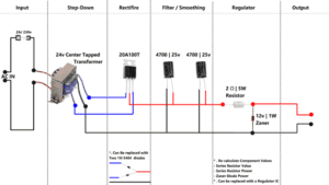
RTU5024 Power supply diagram 1
As you can see in the circuit diagram , Wire that comes from the center point of the winding is being used as a ground . Other two wires where connected to anodes of each diode . The cathodes of these diodes are connected together and positive output was taken from it . This diode arrangement is called half bridge rectification. The Output voltage will be around half of the rated voltage of the transformer. E.g – In this case it’s around 17 volts (Open Circuit) .

Half Bridge rectifier Signal Diagram
Working Principle – If you look at the output sine wave from the transformer . Each coil have 90 degree shifted sine wave with the other at a given time. So when one side of the sine wave is present at one coil the other coil will have that sine wave at the other side . Since the diodes will cutoff the negative side of the sign wave .Only the positive side can pass through it. This gives the output which resembles a full bridge rectifier . The difference is that the voltage drop is low compared to a full bridge rectifier .
Linear Power Supply with Normal Transformer
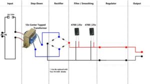
RTU5024 Power Supply Diagram 2
The normal transformer have only one output voltage . Two wires on the secondary side which are connected to each end of the secondary coil provides this output voltage. This transformer need to be used with a full bridge rectification circuit to get the best performance . Here is how build a power supply with a normal transformer.
As you can see in this diagram the output from the transformer connects to the diode bridge . The output was taken from the bridge rectifier .

Signal Flow Full Bridge Rectifier
Working Principle – As you can see in the signal diagram when the sine wave is at the positive side it passes through D2 and goes through the load and it exists through D3 diode . In the negative cycle it passes through D4 and goes through the load and exists trough the D1 diode. Note the current direction is the same . Creating a DC signal at the output.
Considerations
There are few things that need to be taken into consideration when designing power supply for RTU5024 G.S.M controller.
Safety – There need to be safety features available in this RTU5024 power supply circuit. There are few components that can be used as safety components . In this circuit diagram we used fuses in both input and the output of the transformer to prevent any damages to the windings due to over current or short circuit . This also protects other components by cutting of the power in case of a short circuit. Although , There are other components that can be used for the safety , These components will do a good job protecting your components .
Filters – You can use a filter stage at the input of this RTU5024 power supply to prevent electromagnetic interference . You can buy it as a unit . Google “EMI filters” . This unit will prevent the line noise from entering the RTU5024 power supply circuit . Also you can use a filter circuit on the output . However the component values need to be calculated . Because each noise is unique have a different frequency and different amplitude .
Wires / Traces – You have to use wires that can carry the current required by the RTU5024 G.S.M relay controller . The copper wire gauge and Amount of copper wires inside need to be taken into consideration . When it comes to the circuit board the trace paths also need to be able to carry the current that required by the RTU5024 G.S.M relay controller . The trance path width and depth need to be taken in to consideration . If trace paths or wires are too small , high current flow can burn the wires or trace paths before the fuses are blown.
Ventilation – The panel box need to be properly ventilated to protect the transformer from over heating . Over heated transformer can damage the insulation and create short circuits. If you are using a rectifier like we used in this project . You need to fitted it to a good heat sink to protect it from overheating . Since , RTU5024 doesn’t take much current you don’t need a fan to prevent over heating . But , This situation can be changed. If you are using a small transformer to draw the current that required for RTU5024.
Conclusion
 Since , RTU5024 has a G.S.M module. When designing a power supply for RTU5024 you need to focus more on the electrical noise filtering . That is one of the reasons we used a linear power supply over S.M.P.S . Because , Lot of S.M.P.S available in the market have very noisy output . Good S.M.P.S can cost you a lot . You can build your own linear power supply without much effort . If you can use a E.M.I filter at the input of the linear power supply , You don’t have to worry about line noise . The transformer should be able to output the current required without much effort . If the transformer heats very quickly , That transformer need to be replaced with a one that have high current output . Don’t forget to drill some holes in the panel box to allow heat to flow outside .If you can , Monitor the output signal using a oscilloscope both with load and without load.