 Did your Blue Yeti microphone stop working ? , You came to the right place we will discuss how to fix it .Blue microphone Yeti is one of the famous microphone brands available today . It’s one of the best quality microphones around .However , These microphones can go bad due to many reasons . Most of the time it’s a single component that go bad and people throw it away. Because they don’t know how to fix it . Most of the time it’s a simple fix that can be done by anyone even without a knowledge in electronics and repair . Here in this article we will discuss how to troubleshoot and find the issues and how to fix your Blue Yeti microphones.There are mainly two sections inside these microphones . The Digital board and the Analog board .For the simplicity of this article . We are only going to focus on the digital board of the Blue Yeti microphone .
Topics
• Causes of not working Blue Yeti microphone.
• How to disassemble Blue Yeti microphone.
• How to Troubleshoot Blue Yeti microphone – Online.
• How to Replace The USB port of Blue Yeti microphone.
Cause of Blue Yeti microphone not working
There are many causes that can play a role when it comes to not working Blue Yeti mictophone. However most of the time misuse of the microphone cause lot of these problems . However , There are no instructions that tells the users how to use the microphone safely either.Here are some of the main cause that cause your microphone to stop working.
Damaged USB cable

Blue Yeti USB mini Cable
The original USB cable that comes with Blue Yeti microphone is pretty strong . But , These USB cables can be damaged . E.g – If you bend the USB cable too much or pull the USB cable . There also the environmental factor. Hot weather can harden the insulation of the wires .Once the insulation is hardened , bending of the cable can tear the insulation . If you wants to know whether your USB cable is the cause of not working Blue Yeti microphone or not . Check the troubleshooting section in this article. You can find replacement USB cable from Here .
Damaged USB port

Blue Yeti USB mini port
Frequent pulling and plugging of the USB cable from the microphone side can damage the USB port inside the microphone . The pins inside the USB port are gold plated to prevent the oxidization . However , This plated gold can wear out every time when USB cable being plugged or unplugged due to the friction between contacting pins. Once the golden plate is gone , The port pins will oxidize .This may prevent the contact between the pins. Read the trouble shooting section to know how to find out is this the reason that cause your Blue Yeti microphone not working.
Damaged Microphone digital board

Damaged Blue_Yeti_Board
The digital board of the Blue Yeti microphone is where all the digital parts of the microphone are placed . The digital board of the microphone can be damaged due to may reasons . Short circuits can damage the trace paths (copper paths on the PCB) . Some times insects like ants can damage the PCB inside the microphone (By creating short circuits).
Damaged Microphone components

Damaged Blue Yeti components
Inside the microphone there are many components resistors , capacitors , ICs , Transistors and many more . If any of these components go bad which can result not working microphone. These components can go bad for no reason simply due to age and environmental conditions can lead to damaged components . Some of these damaged components can result short circuits . Read the troubleshoot section on how to check for bad components .
Checking USB Cable
Before disassembling and troubleshooting Blue Yeti microphone . Lets check the USB cable first .Because , If USB cable is the problem , This will be a easy fix. You can check the USB cable by plugging it to a another device that uses USB mini port . If that device works , The fault is not due to damaged USB cable . If the device doesn’t work , The USB cable is more likely caused your microphone to not to work.
But , If you wants the to check the USB cable properly . You need a multimeter and the female USB sockets of the jacks at each end of the USB cable . USB type A female (Pin Type) and a USB mini type B socket . This allows the multimeter probes to access to the pins inside the male jacks of the USB cable.

Plugging the USB sockets to the cable
• Plug the Female sockets to the corresponding male jacks .
• Put your Multimeter on continuity checking mode .
• Put one probe in pins of one socket and the other probe in pins of other socket .

Checking pin continuity
• Starting from one side check the continuity between pins from one socket to the corresponding pins on other socket . This photo shows the pin connection between sockets . If there is continuity , You will hear a buzzer sound.
If the buzzer didn’t make a sound upon a checking of pins .This means that there is no continuity between those pins . Which means a broken wire . In that case you have to replace the USB cable.
You can Find a replacement USB cable from Here !
Disassembling Blue Yeti Microphone
In order to preform further troubleshooting we need to disassemble the microphone . It’s a quite easy process . Disassembly of this microphone only requires a Phillips screwdriver.

Knob Screws holding the Microphone
• Remove the two knob screws that holding the microphone from the stand . You can remove it by hand.
• Once you done that , Pull the microphone out of the stand . Make sure to remember the order of the washers . It will help you with the assembling of the microphone.

Removing Blue Yeti Microphone Knobs
• You need to remove all the knobs on the microphone first . The safest way to remove them is by wrapping a cloth around the knob and pull them out with a pair of pliers . Don’t put too much force of the handles of the pliers , It may damage the knob .
• Turn the microphone upside down . You will see two screws . There is another one under the mounting hole of the microphone which is not visible due to the rubber pad inside it. You can use a pry tool to remove that pad or you can put your screw driver right through the pad ( Not recommended .This may damage the rubber pad .)

Screw locations
• Unscrew all the screws at the bottom of the microphone .
• Pull the body of the microphone out safely .
Removing the digital board

Removing Digital Board of Blue Yeti
• The Digital board of the blue yeti microphone is held by four Phillips screws . Unscrew them .
• Pull the board out .
Removing the Analog board

Removing The Analog Board of Blue Yeti
• The Analog board of the blue yeti microphone is held by four Phillips screws . Unscrew them .
• Make sure to mark the colors of the wires in the connectors (If it’s not already marked) .
• Remove the connectors gently . Don’t pull the connectors from their wires . Pull them by the connector body .
• Once you done that , You are free to remove the analog board .
Troubleshooting Blue Yeti Microphone
Most of the time the faults occur on the digital board of the Blue Yeti microphone . To fix the microphone we need to preform some troubleshooting . follow the above steps and disassemble the microphone and remove the digital board . There are two methods when it comes to troubleshooting. Offline and Online . In offline method we check the continuity and the resistance of the components while the microphone is not connected to the PC . This is by far the safest way to check the Blue Yeti microphone (Watch the video if you are interested in this method ). However , In this article we are going to focus on online or live testing of Blue Yeti microphone . This allows us to check for faults very quickly . But , You need to be extra careful with the handling of the probes of the multimter .
Live Troubleshooting
In live troubleshooting we measure the voltages of the Blue Yeti microphone while it’s connected to the PC . Plug the blue yeti microphones digital board to the PC . Put Your multimeter in DC voltage mode . We are only going to focus on the power circuit and it’s components. Because , it require special equipment to check the signal circuit .
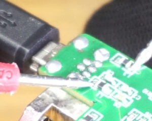
Checking the voltages at USB port

Blue Yeti Troubleshooting USB Port
• Place your red and black probes as shown in the image and check the voltages .
• The multimeter should display a value near 5.0 volts .
Conclusion – If the above voltage is not displayed , Which means the USB cable or USB port is bad . Sometimes the both .
Fix – Check your USB cable . If it’s good , Try to re-solder the USB port and check the voltages again . If the voltages are still not present , Replace the USB mini port .
Checking the voltages at the coils
There are SMD coils on each power line to filter out the electrical noise that comes through USB port of the PC . We are going to check whether these coils receive the voltages correctly or not .
Step 1

Troubleshooting PCB Step 1
In this step we are going to check the trace path connection between the USB port power pins and the pads of the SMD coils ( L3 and L1 ) .
Step 2

Blue Yeti Troubleshooting PCB Step 2
In this step we are going to check the trace path connection between the USB port power pins and the pads of the SMD coils ( L3 and L2) .
• Place your red and black probes as shown in each step and check the voltages in each step.
• The multimeter should display a value near 5.0 volts in every step.
Conclusion – If the voltage is not displayed on the Multimeter , You may have a bad trace paths in the PCB . However , The cause of the bad trace paths may due to a short circuit .
Fix – If there is no short circuit , Connect the pin of the port to the pad of the SMD coil by soldering a wire between them .
Checking the voltages after the coils
We are going to check whether the coils are good or bad .
Step 1
Blue Yeti Troubleshooting coils
In this step we are going to check the condition of the L3 coil . Put Red probe on the L1 coils first pad and black probe into L3 coils second pad .
Step 2

Troubleshooting coils Step 2
In this step we are going to check the condition of the L1 coil . Put Red probe on the L1 coils second pad and black probe into L3 coils first pad .
Step 3

Blue Yeti Troubleshooting coils Step 3
In this step we are going to check the condition of the L2 coil . Put Red probe on the L2 coils second pad and black probe into L3 coils first pad .
• Place your red and black probes as shown in each step and check the voltages in each step.
• The multimeter should display a value near 5.0 volts in every step.
Conclusion – If the voltage not displayed on the multimeter , You may have a bad SMD coil . However , The cause of the bad coil may due to a short circuit .
Fix – If there is no short circuit , Replace the SMD coil . (The coil values will be posted in this article in near future .)
Short circuit checking
Before replacing anything in the Blue Yeti microphone we need to make sure that there is no short circuit .If there is a short circuit , Finding the component that causes short circuit is the key to fixing Blue Yeti microphone. Damaged IC , capacitor or any other component can cause the short circuit . Since , This cause high current flow through the components along the path of the short circuit . The components that are connected in series can be damaged .Here is how to check for short circuits in the power side of the Blue Yeti microphone. Put your multimeter into resistance checking mode and check the resistance between these points.
Step 1

short circuit check Step 1
In this case we are checking the short circuits after the L1 coil by checking the resistance between L1 coils second pad and ground. Put the red probe on the second pad of the L1 coil and black probe into first pad of L3 coil .
Step 2

Blue-Yeti short circuit check Step 2
In this case we are checking the short circuits after the L2 coil by checking the resistance between L2 coils second pad and ground. Put the red probe on the second pad of the L2 coil and black probe into first pad of L3 coil .
The resistance value that displayed on the multimeter should be over 1Kohm . However the resistance value will change as it charge the capacitors .
Conclusion – If the resistance valve is near zero ohm , You have a short circuit .
Fix – However the fixing Blue Yeti microphone in this case is not easy . If you get a short circuit in the first step , You have to remove the SMD C6 (value : 600 uf / 10v ±20%) capacitor and check for the short circuit again . If the short circuit still persists , You may have a bad U2 IC (Part No : CM6400) . If the removal of the capacitor fix your short circuit , Replace the capacitor with a new one with the near or exact value . The SMD package of the capacitor is 0603 or 1508 .

Blue-Yeti short circuit troubleshoot
To fix the short circuit in step 2 you have to use a different method because there are many components along that power line . You have to use the inject method . In this case we supply a 5v power via variable power supply (See the image) . We increase the current gradually .Same time we touch each component by hand . If any of the component gets heat abnormally that could be the cause of the short circuit . Then you can remove that component and check for short circuit again .
If above solutions doesn’t fix your problem . Here are some of the voltages through out the circuit . You can check these voltages with the Gnd ( – ) pin and come to a conclusion your self .
Replacing the USB Port
If you found out that USB port is the cause of the problem . You have to replace it . The replacement parts links are in the bottom of this article. First we need to de-solder the USB mini port in the digital board of Blue Yeti microphone .
De-Soldering USB mini Port Method 1
You need a soldering iron , De-soldering pump and a piece of soldering wire (leaded and with flux) .The reason we are going to use soldering wire is to introduce it to the existing solder in the PCB . This process will make it easy to de-solder the USB port .

Introducing leaded Solder wire to pads
• Turn on your soldering iron .
• Heat the pads of the USB port PCB layout . Then feed the solder wire to the pads .Do this to all the pads of the USB port layout .
• Now Take the de-Soldering pump and charge it by pushing the rod until you hear the clicking sound.

Blue Yeti using de-soldering pump
• Take the soldering iron and melt the solder at the pins of the USB port . Once the solder is melted . Take the soldering iron away and cover the melted solder pad with the nozzle of the de-soldering iron.Once you done that push the button on the de-soldering iron. This will suck the melted solder into the de-soldering pump . These steps need to happen very quickly before the melted solder becomes solid .
• Do this to all the pins . Do it few times until you can see the other side through the pads (vias in pads ).
• Once you done that pull the USB port from other side while heating the pins using the soldering iron .
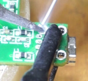
De-Soldering USB mini Port Method 2
In this case we are going to de-solder the USB port using the hot air gun .

Applying solder flux
• Apply some flux into the pads of the USB port .

Applying hot air to USB port
• Turn ON your Hot air gun . Wait until the temperature is reach to desired level .
• Then apply the heat to the USB port pins from the opposite side of the board. Don’t apply the heat to a one place for a while .
• Once the solder start to melt pull out the USB port from the other side using a tweezers . If there is any solder remains in the pads. Remove them using the help of de-soldering pump .
Soldering New USB Port
Once you done removing the old USB port make sure to clean the pads (Vias in pads) of the USB port layout in the PCB .You should be able to see through the pads . For soldering we are going to use two types of soldering wires 0.6mm and 0.3mm (Leaded with flux ). The 0.6mm soldering wire is for the body pins of the USB port and 0.3mm is for the data and power pins of the USB port.

Placing USB port
• First , Make sure the pins of the USB port are not bent . Align the Power and the data pins of the USB port with the holes in the PCB . Push the USB port while moving it side to side . Properly seat the USB port in the PCB . Turn the PCB around and see whether the pins can be seen from the other side.
Soldering Body pins with 0.6mm
• Use a clip to hold the USB port at the proper position .
• Turn ON your Soldering iron and start soldering from the body pins .Use 0.6mm soldering wire for body pins . You can remove the holding pin when you done soldering the body pins .

Soldering data and power pins with 0.3mm
• Then , Solder the power and data pins with the 0.3mm soldering wire.
Once done soldering , Clean the solder area with some Isopropyl alcohol (Use a brush). Make sure there is no solder residue or solder bridges made between pins .
Software Issues
If software issue is the cause of Blue Yeti microphone not working , You will clearly see the light of the microphone when plugged to the PC . But , The computer fails to identify the microphone . However, The newer versions of Windows or Mac operating systems will detects and installs the drivers as soon as you plug the microphone for the first time. Older versions of Windows or Mac OS operating systems will not be able to do that . Here is how to download and install the divers if your Blue Yeti microphone not detected by the PC .
For Blue Yeti microphone – Read the instructions from Here
For Blue Yeti Pro –
• Plug your Blue Yeti Pro microphone to the PC .
• Open your web browser and go to Here . Scroll down and click on “Download: button in front of “Yeti Pro Driver” label .
• Open the downloaded zip compressed file .
• If you are using a Windows OS double click on “BLUE_YetiPro_DriverSetup_v2.23.0.exe” .
• If you are using a Mac OS go inside the “_MACOSX” folder and double click on the “._BLUE_YetiPro_DriverSetup_v2.23.0.exe” (Since , This is a .exe file you may have to use software like “Vine for mac” to install this driver.)
Replacement Parts
Here are the links for Blue Yeti microphone’s USB mini port . These are the links we were able to find . However , The Digikey product only have two body pins.
Conclusion – Blue Yeti microphone fix
 There are many reasons that can cause your Blue Yeti microphone to stop working . Whatever the reason is , It’s impotent to identify what causes the problem by troubleshooting . Some repairs can be easily done some can be hard to preform . Most common cause of not working Blue Yeti microphone is due to bad USB port . To avoid damaging your USB port limit the amount of times that you plug and remove USB cable from the microphone side. There also the software driver issues . Most uncommon cause of microphone not working is due to EEPROM IC issues or USB interface IC issues of Blue Yeti microphone . If the issue is with the analog board of the Blue Yeti microphone you will hear noise when recording or some times very low amplification in the recording .